

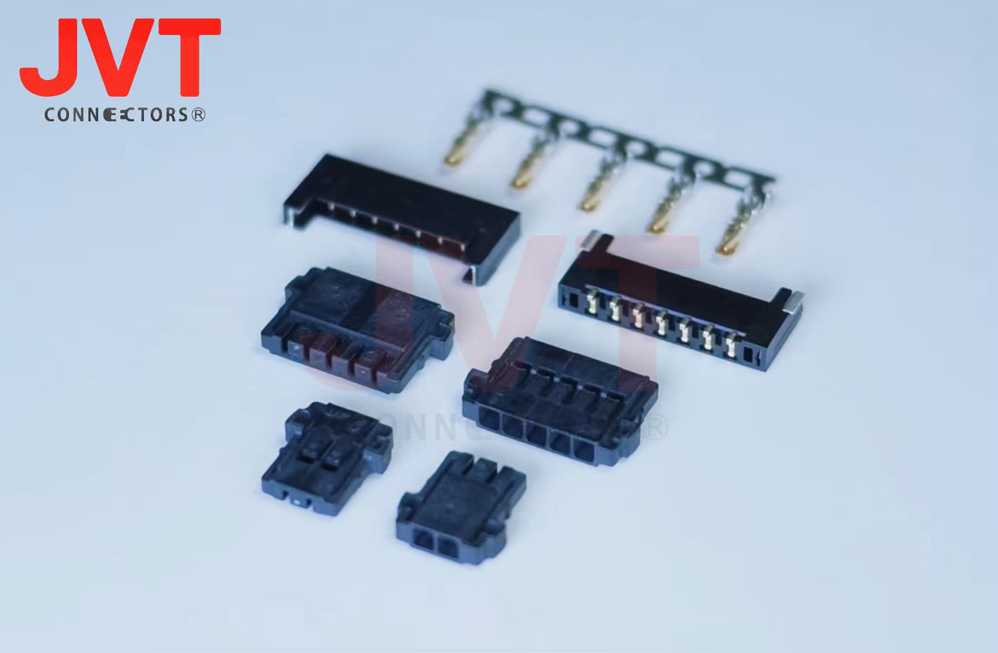
2.0 mm Wire to Board Connector: A Practical Guide to Pin Configurations and Applications
Rows, positions, keying, and the harness documentation that keeps a five-hundred-unit build from turning into a five-hundred-unit rework
A 2.0 mm connector is rarely the most demanding part on a board, but it is often the one that decides whether a harness can be assembled and serviced. Most of that difficulty sits in the harness drawing and the pin assignment, not in the connector itself.
A 2.0 mm wire to board connector is one of the workhorses of internal wiring, large enough to handle comfortably and small enough for a dense appliance board. This guide covers it in three parts: the pin configurations the family is stocked in; the single-row and double-row decision; and the applications where a 2.0 mm part is the practical choice.
The difficulty is not finding a part, but choosing a pin configuration that matches the harness, the assembly sequence, and the service procedure.
Pin configuration sounds like a simple count, and it is treated that way far too often. In reality, the arrangement of positions, the presence of keying, the row structure, and the way the harness drawing numbers the contacts all interact.
A connector that is electrically correct can still be built wrong if the harness drawing and the PCB silkscreen number the pins differently, and that mistake tends to be discovered at the end of the line rather than at the start.
This guide covers the pin configuration decisions that matter for a 2.0 mm wire to board connector, then maps the pitch to the applications where it is most often used.
Pin Configurations in a 2.0 mm Wire to Board Connector
Four properties define a configuration: the number of positions, the row structure, the keying or coding, and the orientation of the wafer. Everything else, including plating and packaging, is a variant of those four.
Position count
Position counts at this pitch commonly run from two up to the high teens, with the exact range depending on the family. The count you choose should come from the circuit requirement plus a deliberate decision about spare positions.
Leaving one or two spare positions is cheap at the design stage and expensive later, because adding a position usually changes the housing, the wafer, and sometimes the board outline.
Row structure
Single-row parts are easier to inspect, easier to probe, and easier to document. Double-row parts halve the length of a large interface but double the insertion force and place the inner row where a probe cannot easily reach.
At 2.0 mm, a double-row twenty-position part is a compact solution; a single-row twenty-position part is a long, mechanically flexible interface that can be awkward to mate squarely.
Keying and coding
Keying prevents a harness from being plugged into the wrong header. At 2.0 mm there is enough housing material to mould a keying rib or a coding block, and enough variants exist that two connectors with the same position count can be made mutually incompatible. In a product with several similar harnesses, keying is cheaper than any amount of labelling.
Orientation
Straight and right-angle wafers change the cable path. A right-angle part keeps the harness close to the board, which is useful in a shallow enclosure, but it also concentrates the bend immediately after the housing. A straight part gives the cable more room to turn but adds height. Choose with the enclosure in front of you, not from the catalogue thumbnail.
Single Row or Double Row: How to Decide
The choice is usually made on length, and it should be made on insertion force and inspection instead.
A single row is the right answer when the connector sits at a board edge, when the harness is assembled by hand in an open fixture, and when the position count is modest. It is also easier to rework: a single row of pads can be touched up with a normal iron, while an inner row on a double-row part may be inaccessible without removing the connector.
A double row earns its place when the interface is long enough that a single row would dominate the board edge, or when the enclosure width is the binding constraint. The cost is insertion force. Two rows of contacts require the operator to push harder and to keep the housing square, and a part that is mated at an angle can bend terminals in the inner row without any visible sign.
| Criterion | Single row | Double row |
|---|---|---|
| Board length | Longer | Shorter |
| Insertion force | Lower | Higher |
| Inspection | Straightforward | Inner row restricted |
| Rework | Easier | Harder |
| Best for | Edge-mounted, hand-built harness | Wide interfaces, shallow enclosures |
Pin Assignment and Harness Documentation
The most common manufacturing defect in connector assemblies is not a bad crimp. It is a harness wired to a different pin numbering convention from the one on the board. The connector is fine; the documentation is not.
Two conventions exist in common use: numbering along one row and then the next, and numbering in a zig-zag that alternates between rows. Both are legitimate, and both appear in datasheets.
The only safe approach is to put the pin-one marker on the PCB silkscreen, on the assembly drawing, and on the harness drawing in the same orientation, and to state the convention explicitly rather than relying on a picture.
It also helps to define pin one physically. A moulded triangle, a chamfered corner, or a marked first position gives the operator something to align to without reading a drawing. If the housing has no such feature, a small silkscreen mark beside the connector is better than nothing, but it is less reliable because conformal coating and reflow discolouration can obscure it.
- State the numbering convention in words on the drawing, not only in a picture.
- Put pin one on the silkscreen in the same orientation as the drawing.
- Check the harness drawing against the board drawing with both documents open, not from memory.
- Ask the harness house to confirm the convention in writing on first article.
Retention and Sealed Variants in the 2.0 mm Family
Because 2.0 mm is a popular pitch, the family around it tends to be broad. Two variant types are worth knowing about before you specify.
The first is the high-retention variant, usually achieved with a stronger latch, a secondary retainer, or a housing geometry that resists side pull. These are useful in appliances with moving parts and in transport applications where the harness is subject to vibration.
The second is the sealed variant. Some 2.0 mm families include gasketed or potted versions intended for wet or dusty environments, and these have been used in automotive sensor and climate applications. If the product needs sealing, specify it as a system requirement, including the wire seal, the housing seal, and the panel interface. A sealed connector with an unsealed wire entry is not sealed.
Both variants add cost and often add assembly steps. The decision should come from the environment the product actually sees, not from a preference for a rugged-looking part. In a dry indoor appliance, a standard latch with a well-dressed harness is usually sufficient.
Application Notes: Appliances, Automotive, and Industrial
In home appliances, the 2.0 mm wire to board connector typically links a main control board to a display, a sensor cluster, or a valve harness. The environment is humid, the harness is handled during assembly, and the product is serviced occasionally. A positive latch, a housing rated for flammability, and a plating that tolerates humidity matter more than the number of positions.
In automotive accessories, the pitch appears in interior lighting, climate sensors, and camera modules. Here the requirements shift toward vibration, temperature cycling, and where necessary sealing. Our automotive connector range is built around those conditions. The harness is often shorter and more rigid, so the connector must tolerate a stiffer cable without transferring load to the solder joints.
In industrial equipment, the pitch is used for sensor and control links inside enclosures. The dominant concerns are vibration, EMI, and service access. Shielding is usually handled at the cable level rather than the connector, so the connector's job is to maintain a stable contact through movement and to be easy to disconnect when a module is replaced.
Manufacturing Background at JVT
JVT Connectors has been manufacturing in Dongguan since 2006 and operates a 6,500 square metre plant with a branch in Wujiang, Jiangsu.
Production includes more than twenty injection moulding machines, more than twenty stamping presses, and more than fifty automatic pin insertion machines. The quality system covers ISO 9001, ISO 14001, IECQ QC080000, and IATF 16949, and products are tested by UL and SGS.
The company's range covers nineteen pitch steps from 0.60 mm to 6.35 mm, and 2.0 mm is one of the broadest families in that range, with multiple housing styles and sealed variants.
JVT is a connector manufacturer rather than a distributor, and its stated direction is import substitution against established families from Molex, JST, TE, HRS, and AMP. For a 2.0 mm programme, that means the discussion can cover pin configuration, keying, and housing material rather than stopping at a part number.
If a configuration does not exist in the standard range, the question becomes one of tooling. Moulded keying and position counts outside the standard set require a new tool, and the economics depend on volume. That conversation is worth having early, because a custom housing with a twelve-week tooling lead time can change a product schedule.
Frequently Asked Questions
How many positions can a 2.0 mm wire to board connector have?
The standard range varies by family, commonly from two positions into the high teens. Above that, a double-row part is usually more practical. Confirm the exact range for the family you intend to use rather than assuming it continues indefinitely.
Can keyed and unkeyed housings be mixed in the same product?
You can, but it defeats the purpose of keying. If two harnesses could be swapped, key both of them differently. If only one interface exists, keying adds cost without benefit.
What is the best way to avoid a reversed harness?
Physical keying plus an unambiguous pin-one mark plus a written numbering convention on the drawing. Any one of the three alone will eventually fail; together they make a reversal unlikely and easy to catch at first article.
If you have a 2.0 mm wire to board connector configuration in mind, send the circuit list and the harness drawing and we will confirm which standard housings and wafers cover it without new tooling.
Browse 2.00 mm Configurations View All Wire to Board Series