

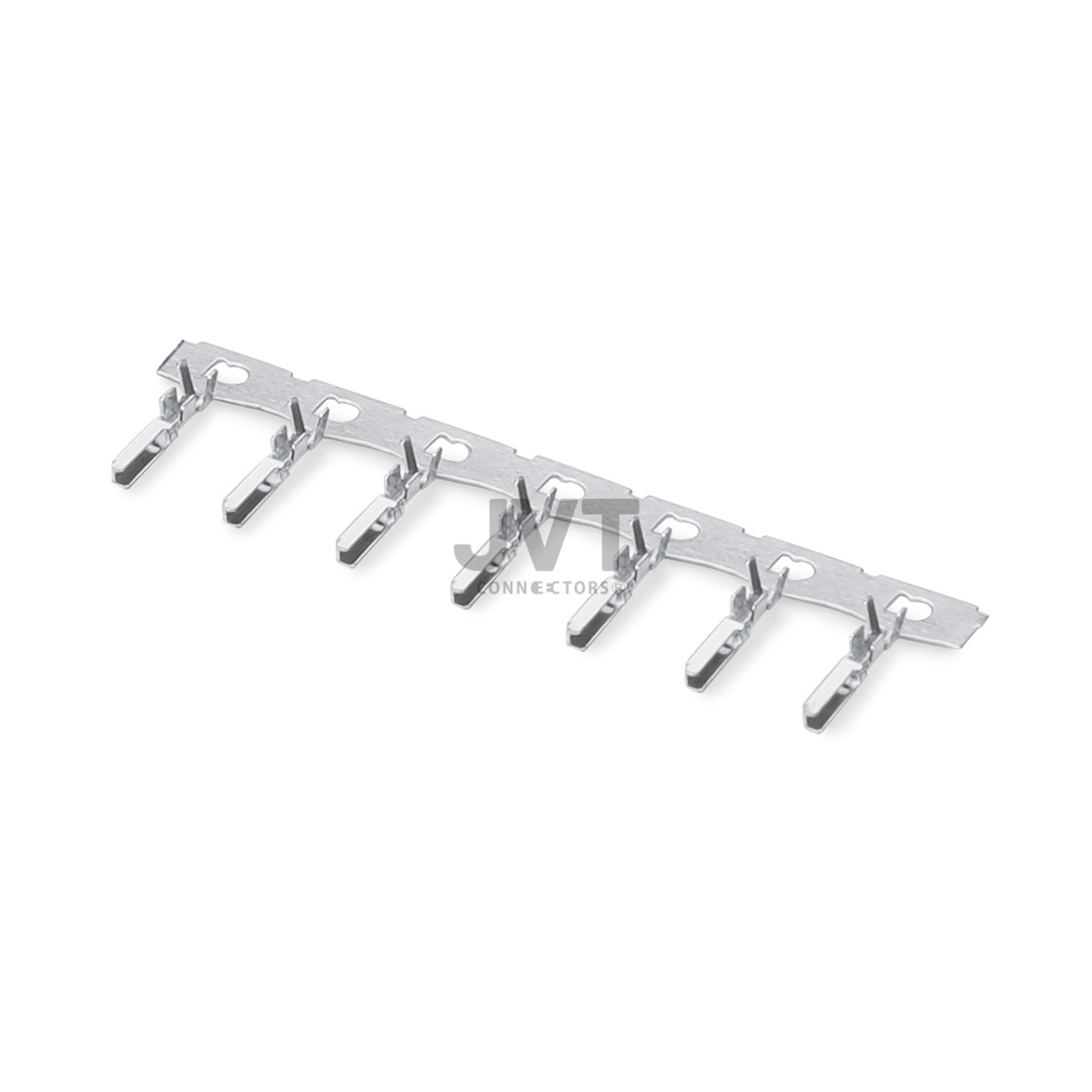
A robot vacuum motor connector spends its life doing something unusual: switching. A robot vacuum starts and stops its brush motor and its fan motor whenever it changes direction, climbs a threshold, or decides the floor is too wet for suction, and that adds up to a very large number of switching events over a service life. On a cordless cleaning appliance program, the customer's board was small, the internal routing was tight, and the previous connector had been selected for space alone. Field returns showed intermittent motor behaviour that traced back to the interface, and the brief to us was to find a smaller pitch family that would still hold up.
This case study covers what a brushless motor board in a cleaning appliance actually needs from its connector, why high frequency start-stop changes the design question, and what the program achieved. It is written for engineers and buyers specifying connections for robot vacuums, stick vacuums, and similar cordless cleaning products.
What Makes a Robot Vacuum Motor Connector Different
The signals on a brushless motor board are not high current in the absolute sense, but they are high frequency and they are switched without warning. Three characteristics separate this application from a static control board.
- Switching cycles, not duty cycles. A robot vacuum can start and stop its motors hundreds of times in a single cleaning run. Each event is a small thermal and mechanical pulse at every contact in the path.
- Vibration from the chassis. The motors, the wheels, and the brushes all put energy into the frame, and the connector carries it as micro-movement at the contact interface.
- Rubbish on the other side of the board. Dust, pet hair, and moisture from mopping pads reach the electronics compartment more often than the product literature suggests.
Stack those three together and the design question stops being about board area. It becomes about whether the contact interface can hold its electrical position through all of that movement, and that is decided by terminal design rather than by pitch.
Why We Moved This Board to the 1.5 mm Family
The customer's board was already in a 1.5 mm class of pitch, and the request was not to shrink further but to make the interface reliable. We supplied the JVT1503 series, a 1.5 mm pitch wire-to-board family, and specified it together with a terminal that provides consistent normal force.
Consistent contact force through thermal movement
The terminal spring is what maintains the electrical path when the housing expands and contracts. If the spring force changes with temperature, contact resistance changes with it, and on a motor feedback line that shows up as intermittent behaviour rather than as an obvious failure.
Retention that survives a drop
A cleaning robot is picked up, dropped, tipped, and pushed into furniture. The housing retention and the latch design are part of the reliability specification in this application, not a convenience feature.
Compact routing inside a crowded chassis
With a 1.5 mm pitch family, the multi-position motor and sensor interface fits along the board edge without forcing the harness to loop around the battery pack. On a robot vacuum, every millimetre of internal cabling is a potential pinch point, so routing simplicity translates directly into a lower field failure rate.
Interface configuration for this project
Connector family: JVT1503 series on 1.5 mm pitch, used at the brushless motor control board.
Signal set: motor phase and feedback wiring, sensor inputs, and the supply for the motor driver stage.
Duty profile: frequent start-stop across a cleaning run, with continuous vibration from the motors and drive wheels.
Application scope: cordless cleaning appliances, robot vacuums, stick vacuums, and similar compact motor driven products.
What the Program Reported
The findings below are the ones reported for this cleaning appliance program. They describe this design and this board geometry.
| Item | Previous interface | JVT1503 series |
|---|---|---|
| Behaviour under frequent starts | Intermittent motor behaviour in the field | No contact fault reported across the production run |
| Pitch | Compact but unreliable | 1.5 mm, small envelope with stable contact force |
| Internal routing | Harness looped around the battery pack | Single run along the board edge |
| Product coverage | Limited to one model | Extended across the cordless cleaning range |
| Materials data | Collected case by case | RoHS and REACH documentation supplied |
The customer's engineering team made one comment that stuck with us. They said the change was invisible to the end user, which is exactly the point. A connector on a motor board should never be the reason a product develops a reputation.
Where the Motor Interface Sits Inside a Cleaning Appliance
It helps to be clear about which connectors actually live in a robot vacuum, because they do not all carry the same risk. The interface at the brushless motor control board handles signals and the driver supply. The battery pack interface handles real current and is usually a different, larger family. The charging contacts on the underside are a mechanical design problem more than a connector problem, and the sensor wiring for cliff detection and bumper switches is a third, low current path.
Projects go wrong when those four are treated as one decision and a single small family is pushed onto every position on the board to save part numbers. The motor interface has to hold its contact position under constant switching and vibration, and it is worth spending the small extra board area that a family with a stable terminal spring requires. The sensor paths can use a finer pitch without any penalty at all, because they carry almost no current and they rarely move.
Splitting the board this way also simplifies fault finding. If a unit loses suction but keeps navigating, the problem is in the motor path. If it stops recognising a drop-off, it is in the sensor path. A design where every signal shares one connector family makes both symptoms look identical on the test bench, and that costs more time in service than the extra part numbers ever cost in procurement.
Why Choose JVT as Your Long-Term Interconnect Partner?
JVT is the brand of Dongguan JVT Connectors Co., Ltd., a connector manufacturer founded in Dongguan, Guangdong in 2006, with a 6,500 square metre plant and a branch in Wujiang, Jiangsu. Injection moulding, stamping, and automatic pin insertion run in our own factory, supported by more than twenty injection moulding machines, more than twenty stamping presses, and more than fifty automatic pin insertion machines. Our quality and environmental systems are certified to ISO 9001, ISO 14001, IECQ QC080000, and IATF 16949, and our products are tested by UL and SGS.
Our pitch coverage runs across nineteen steps from 6.35 mm down to 0.60 mm, which means a customer can move a single board from 2.00 mm to 1.50 mm, or 1.27 mm to 1.00 mm, without changing supplier. Product families include wire-to-board, wire-to-wire, board-to-board, IDC, pin header, DC connectors, board-in terminals, FFC/FPC, and the terminal series, and our application ranges cover home appliances, consumer products, industrial equipment, power tools, automotive, lithium battery 3C, low-altitude flight, power module, and new energy.
For a cleaning appliance board, the natural entry points are the 1.50 mm pitch series used here, the home appliance connector range that covers the rest of the chassis, and the wider wire-to-board connector families for larger battery and dock interfaces.
Frequently Asked Questions About the Robot Vacuum Motor Connector
Why does a motor connector fail on a cleaning appliance but not on a static board?
Because the failure mechanism is mechanical. Frequent starts introduce repeated thermal pulses at the contact, and the chassis adds continuous vibration. Together they cause micro-movement at the interface, which raises contact resistance over time. A board that never moves does not experience either effect.
Is 1.5 mm pitch too fine for a motor interface?
Not when the current per contact is modest and the terminal design is sound. The pitch sets how much space the interface occupies; the terminal and housing set how reliable it is. Where the motor drive current is higher, the connector is usually split into a signal interface and a separate power interface.
What causes intermittent motor behaviour that only shows up occasionally?
Intermittent symptoms are characteristic of a contact that is electrically stable most of the time and unstable during vibration or thermal movement. It is worth checking the connector interface before replacing the motor driver, because the connector is cheaper to rule out and easier to inspect.
Can the same family be used across several cleaning models?
Yes, and reusing one family across a product range is a practical way to reduce tooling, crimp validation, and spare parts variety. Where models differ in position count, only the housing length changes.
How do I choose between 1.5 mm and 2.0 mm pitch for a compact appliance?
Start with the board edge length you can spare and the current per contact. If the edge is short and the currents are modest, 1.5 mm pitch is usually the right answer. If the harness carries actuator inrush or the line is already set up for 2.0 mm crimps, staying with 2.0 mm is the more practical choice.
If a cleaning appliance shows intermittent motor behaviour that nobody can reproduce on the bench, start at the connector. Send us your board edge length, current per contact, and position count, and we will recommend a robot vacuum motor connector from the 1.5 mm family with samples for your own endurance testing.
Open the 1.50 mm Pitch Range Talk to an Application Engineer